Citroën Berlingo 3rd generation was produced in 2018, 2019, 2020, 2021, 2022, 2023, 2024. During this time, the model has been restyling. In this publication, you can find a description of the fuses and relays of the Citroen Berlingo 3 with block diagrams, their locations and photo examples of execution. Let’s highlight the fuse responsible for the cigarette lighter.
The purpose of the fuses in the blocks, as well as their number, may differ from the one presented and depends on the year of manufacture, level of electrical equipment and region of supply of your car.
Blocks in the cabin
Fuse block
The main fuse box is located on the left side at the bottom of the instrument panel.
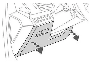
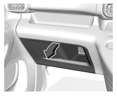
In right-hand drive vehicles, the protective cover or glove compartment must be removed for access.
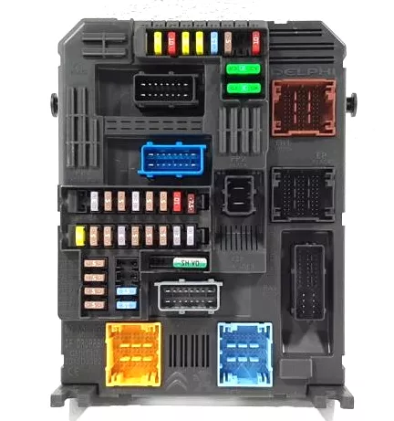
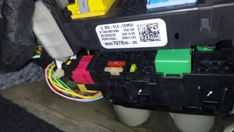
The fuse block itself will look something like this.
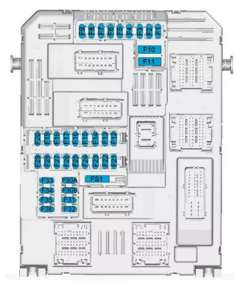
| № | Description |
|---|---|
| 1 | Inductive charging, Interior mirror / Power steering / Selective cruise control / Radar / Diesel exhaust system |
| 3 | Wireless charger for smartphone |
| 4 | Warning |
| 5 | Windshield washer (front/rear) |
| 6 | Windshield washer (front/rear) |
| 7 | Socket behind USB |
| 8 | Rear wiper |
| 10 | Door lock/rear door lock |
| 11 | Door lock/rear door lock |
| 12 | Stop-start system/diagnostic connector module/braking system |
| 13 | Infotainment system / Climate control system |
| 14 | Alarm siren |
| 15 | Automatic transmission, instrument cluster, climate control system |
| 16 | Stop-start system/braking system |
| 17 | Instrument panel |
| 18 | Parking assistant |
| 19 | Steering column electrical equipment / Steering wheel controls |
| 21 | Anti-theft alarm |
| 22 | Camera /Rain sensor/Automatic lighting control |
| 23 | Seat belt reminder, Control module, Start Stop, trailer socket |
| 24 | 7-inch touch screen / Advanced parking assist / Surround view system |
| 25 | Air cushion |
| 26 | Electronic stability control |
| 27 | Alarm / Parking heater |
| 28 | OnStar or BTA module |
| 29 | Infotainment system |
| 32 | Cigarette lighter / Front panel socket |
| 34 | Interior mirror / Parking aid |
| 35 | Light switch/diagnostic connector module/climate control |
| 36 | Lighting devices / USB |
Fuse 32 is responsible for the operation of the cigarette lighter.
Fuse and relay block
This block is located behind the main fuse box.
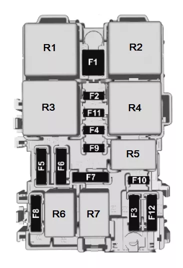
| № | Description |
|---|---|
| F1 | Heater/rear window heater |
| F2 | Heated exterior side mirrors |
| F3 | Power windows – front |
| F4 | Folding side mirrors / Adjusting exterior mirrors |
| F5 | Power windows – rear |
| F6 | Socket in the trunk / Sunroof |
| F7 | |
| F8 | Fuse box (right side of instrument panel) |
| F9 | |
| F10 | Heated seats |
| F11 | Front seat massage function |
| F12 | Hi-fi amplifier |
| Relay | |
| R01 | Seat heating relay |
| R02 | Power window relay |
| R03 | Heater/rear window heating relay |
| R04 | – |
| R05 | – |
| R06 | – |
| R07 | – |
Blocks under the hood
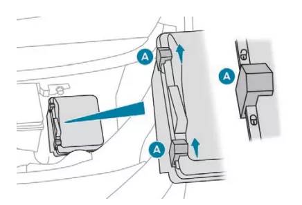
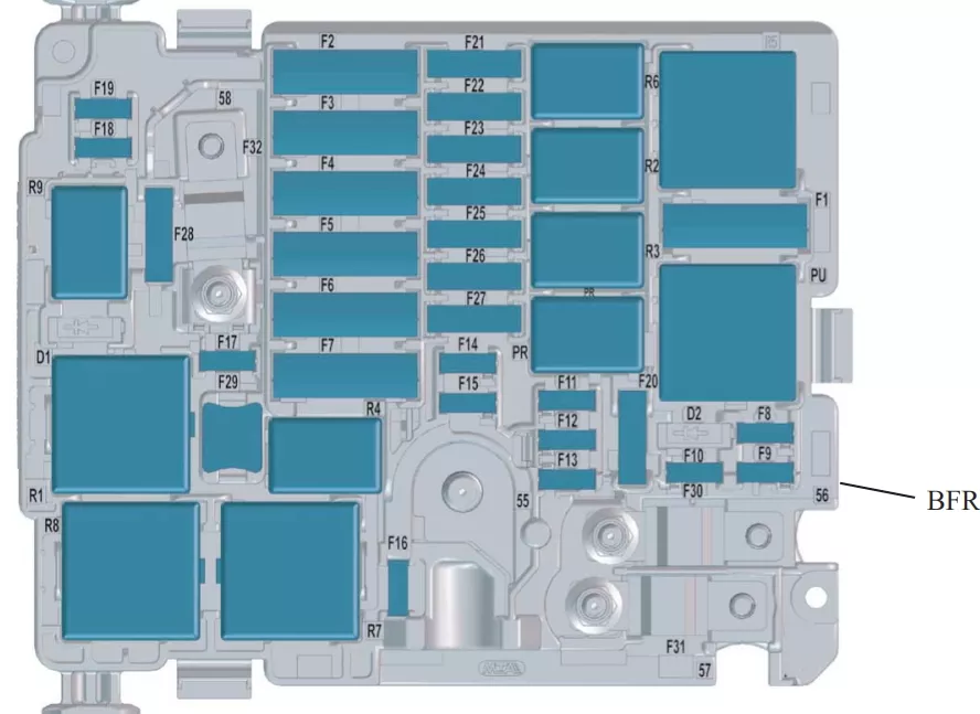
Fuse and relay block
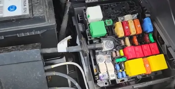
In the engine compartment, under the hood, on the left side, next to the battery, is the fuse and relay box. An example of access is shown in the layout.
| № | A | Marking |
|---|---|---|
| F1 | 40A | Air conditioner fan |
| F2 | 60A | ABS/ESP system computer |
| F3 | 80A | Passenger compartment fuse box 3 |
| F4 | 30A | ABS/ESP system computer |
| F5 | 50A | Intelligent switching unit (Right turn signals, front right side lights, right brake lights, left reversing lights, right fog lights.) 20A Heated windshield |
| F6 | 60A | Two-speed cooling fan control unit (GMV) 20A BVA AxN8 calculator – BVA Ax6III calculator (thermal) |
| F7 | 70A | Intelligent switching unit |
| F8 | 15A | Engine control fuel pump, Pilot operated thermostat – Oil pump solenoid valve (EC flushing – Electric solenoid valve – Intake air flow meter – Oxygen sensors (EP6FADTX), Pilot operated thermostat – Water switching, Electric solenoid (for EB2DT or EP6FDT) l Pilot operated booster pump (for DV6F or DW10F) |
| F9 | 15A | Pilot operated booster pump (DW10F), inlet and outlet valves v solenoid valves – Pilot operated thermostat – Oil pump solenoid valve (EC flushing – Electric solenoid valve – Intake air flow meter – Oxygen sensors (EP6FADTX) Water supply Electric solenoid valve (EP6FDT) |
| F10 | 15A | Engine computer – Diesel fuel flow control pump solenoid – Turbocharger pressure control solenoid valve (DV5R and DW10F) – Thermostat S (DV5R) – Purge heater – Intake and exhaust valve control solenoid valves (EP6FADTX) – TS flush ) |
| F11 | 20A | Engine computer |
| F12 | 5A | Devices – GMV relay – Istars – DMTC, electric water cooling with turbocharging (EB2ADTS and EP6FADTX), intelligent service unit (EP6FADTX) |
| F13 | 5A | Intelligent switching unit |
| F14 | 5A | Battery charge level unit |
| F15 | 20A | Electric windshield heating |
| F16 | 15A | Fog lights 10A Daytime running lights |
| F17 | 10A | GMP BFRM relay diagnostics – BSI1 – Engine computer – Lower Nox sensor (DV5R and DW10 injectors (DV5R) |
| F18 | 10A | Right headlights high beam |
| F19 | 10A | Left headlights high beam |
| F20 | 30A | Engine computer l Booster pump (for ER6EDT) – ignition coils (EB2ADTS and EP6FADTX) |
| F21 | 30A | Starter |
| F22 | 40A | Reserve – Taxi |
| F23 | 40A | Starter / Generator |
| F24 | 40A | Fuse box in the passenger compartment 5 |
| F25 | 40A | Passenger compartment fuse box 3 |
| F26 | 15/20A | Heater |
| F27 | 25A | Intelligent switching unit (Right dipped beam headlight – Right reversing lights – Left fog lights – Left rear position lights – Third brake light.) |
| F28 | 30A | Urea pump power supply and urea pipe heating resistor (UCE or DV5R) – Nox sensor (DW10F) – Engine computer (EP6FADTX) – (BlueInjection, AdBlue) |
| F29 | 40A | Windshield wiper |
| F30 | 80A | Preheating unit |
| F31 | 80A | Switching and protection unit |
| F32 | 80A | Power steering, Left dipped beam headlight – Static turn signals – Side turn signal repeaters – Left turn signals – Front left and rear right side lights – Left brake lights – License plate lights. |
| Relay | ||
| R1 | Engine management computer / Diesel Euro6 (SCR module power supply) | |
| R2 | Air conditioning compressor / Electric windshield heater | |
| R3 | Starter / thermal preparation | |
| R4 | Fog lights / daytime running lights | |
| R5 | Air conditioner fan | |
| R6 | Starter | |
| R7 | Front wiper | |
| R8 | Front wiper | |
| R9 | Headlights | |
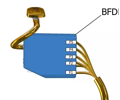
Battery unit
A high-capacity power fuse block is attached to the battery terminal.
| № | A | Appointment |
|---|---|---|
| F1 | 60A | Electric control unit for two-speed fan motor |
| F2 | 100A | Fuse block |
| F3 | 80A | Power steering |
| F4 | 80A | Fuse box in the passenger compartment |
| F5 | 80A | Fuse box in the passenger compartment |