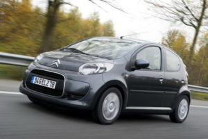
The first generation of the Citroen C1 , a microcar, entered the market in 2005 with 3- and 5-door body options. It was produced in 2006, 2007, 2008, 2009, 2010, 2011, 2012, 2013. After the update, the second generation is produced in 2014, 2015, 2016, 2017, 2018 and to the present. We will consider the diagrams of the Citroen C1 fuse blocks, show the fuse responsible for the cigarette lighter and offer an instruction manual for the 2nd generation Citroen C1.
The location of the blocks and the purpose of the elements in them may differ from the one presented and depends on the year of manufacture, equipment level and delivery region of your vehicle.
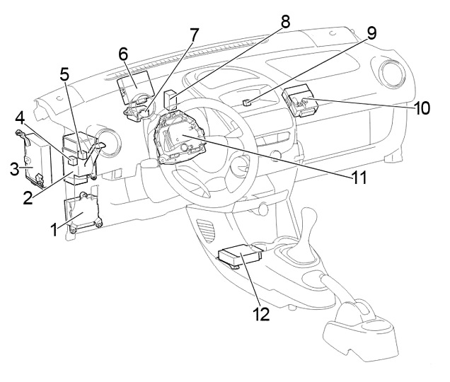
Blocks in the cabin
Arrangement
General scheme
Left hand drive (LHD)
Right hand drive (RHD)
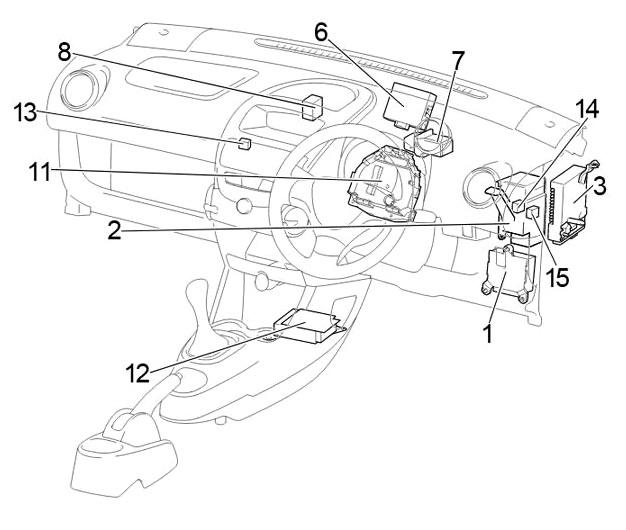
Description
- Power steering ECU
- Central connector
- Multi-mode manual transmission ECU
- Power window relay
- LHD:
Before February 2012: Taillight relay
From February 2012: Rear fog light relay. - Door control system ECU with receiver
- Relay Block #1
- Air conditioner booster
- LHD: fog light relay
- LHD: Running light relay
- Fuse block
- Airbag sensor assembly center
- RHD: Relay Block #2
- RHD:
Before February 2012: Ignition relay (IG)
From February 2012: Power window relay. - RHD:
Before February 2012: Power window relay
From February 2012: Rear fog light relay.
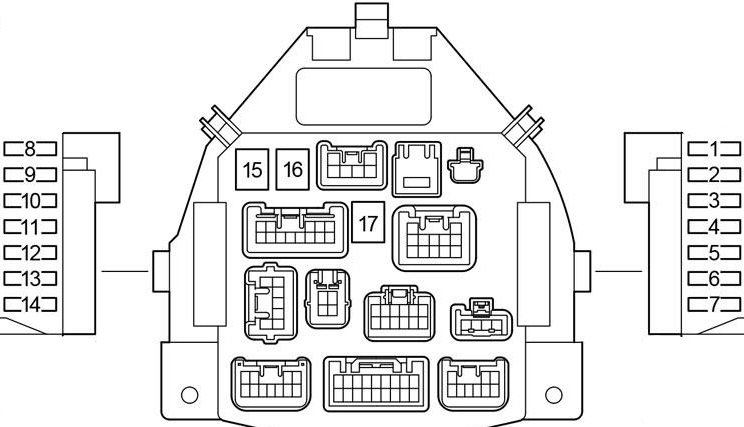
Fuse block
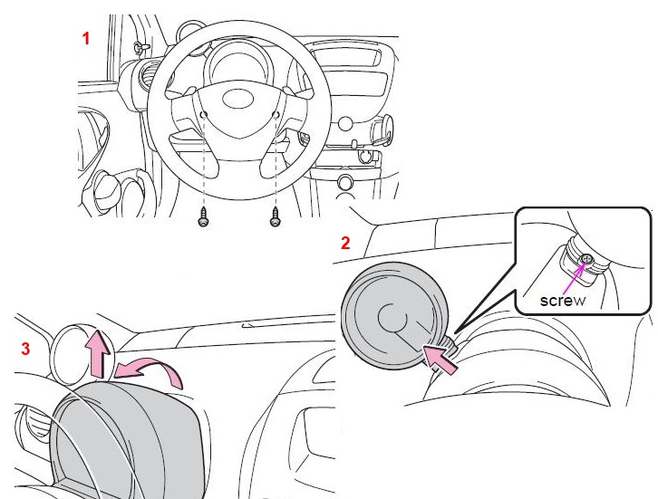
In the cabin, the main fuse block is located on both sides of the speedometer, behind a protective box, and consists of two parts.
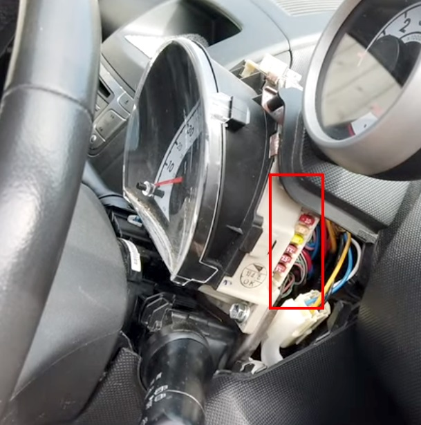
To remove the protective cover, you need to unscrew 3 screws. To do this, you will need to turn the steering wheel in different directions.
Marking
| 1 | 10A STOP – Stop lights, high-beam stop light, anti-lock braking system, multi-mode manual transmission |
| 2 | 25A D/L – Electric door lock system, wireless remote control system |
| 3 | 20A DEF – Heated rear window |
| 4 | 7.5A TAIL – Daytime running light system, taillights, license plate lighting, side lights, headlight level control system, instrument panel illumination |
| 5 | 7.5A OBD – On-Board Diagnostic System |
| 6 | 7.5A ECU-B – Multi-mode manual transmission, daytime running light system, vehicle stabilization system, sensors and instruments, rear fog lamp |
| 7 | – |
| 8 | 7.5A ECU-IG – Anti-lock braking system, vehicle stabilization system, electric power steering, electric cooling system fan. |
| 9 | 10A BACK UP – Reversing lights, power door locking system, wireless remote control system, power windows, rear window defroster, tachometer, air conditioning system, heating system |
| 10 | 20A WIP – Windshield wiper and washer, rear window wiper and washer |
| 11 | 15A ACC – Cigarette lighter , Socket, Audio system |
| 12 | 7.5A IG1 – Windshield wiper and washer, rear window wiper and washer, anti-lock braking system, electric power steering system, electric cooling fan, reversing lights, power door locking system, wireless system, tachometer, air conditioning system, heating system |
| 13 | 15A IG2 – Multi-port fuel injection system / sequential multi-port fuel injection system, SRS airbag system, sensors and instruments, daytime running light system, multi-mode manual transmission |
| 14 | 7.5A A/C – Air conditioning system, electric heater |
| 15 | 40A AM1 – Fuses “ACC”, “WIP”, “ECU-IG”, “BACK UP” |
| 16 | 30A PWR – Power windows |
| 17 | 40A HTR – Heating system, air conditioning system, “A/C” fuse |
Fuse number 11 at 15A is responsible for the operation of the cigarette lighter.
Relay Block #1
Scheme
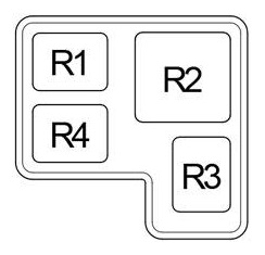
Appointment
- R1 Accessory (ACC)
- R2 Heater (HTR)
- R3 Heated rear window (DEF)
- R4 LHD: Ignition (IG)
Relay Block #2
Scheme
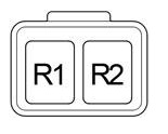
Transcript
- R1 Ignition (IG)
- R2 Fog light (FOG)
Blocks under the hood
Arrangement
General scheme
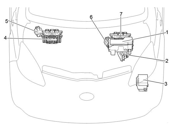
Description
- Fuse and relay block
- Anti-skid system ECU with drive
- Relay block
- LHD: Engine ECU
- LHD: glow plug relay
- RHD: glow plug relay
- RHD: Engine ECU
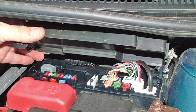
Fuse and relay block
Under the hood, the fuse and relay block is located next to the battery and is covered by a protective cover.
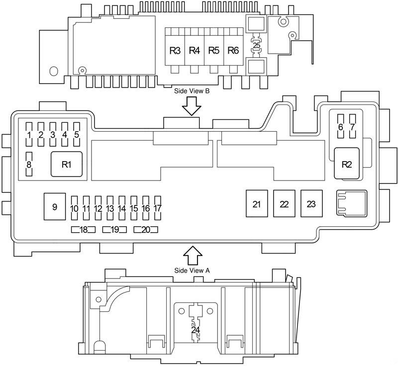
Appointment
| 1 | 15A EFI NO.4 – 2WZ-TV: Multi-point fuel injection system / sequential multi-point fuel injection system |
| 2 | 10A H-LP RH (HI) – Until February 2012: Right headlights. |
| 5A DRL – From February 2012: daytime running lights. | |
| 3 | 10A H-LP LH (HI) – Until February 2012: Left headlight, sensors and instruments. |
| 20A FR FOG – From February 2012: Front fog lights. | |
| 4 | 10A H-LP RH (LO) – Until February 2012: Right Headlights |
| 10A H-LP LH – From February 2012: Left headlight. | |
| 5 | 10A H-LP LH (LO) – Until February 2012: Left headlight, sensors and instruments. |
| 10A H-LP RH – From February 2012: Right headlights. | |
| 6 | 7.5A STA – 1KR-FE: multi-mode manual transmission, multi-point fuel injection system / sequential multi-point fuel injection system. |
| 7.5A FAN NO.2 – 2WZ-TV: Electric cooling fan | |
| 7 | 7.5A EFI NO.2 – Distributed Fuel Injection System / Sequential Distributed Fuel Injection System, Multi-Mode Manual Transmission |
| 8 | 10A EFI NO.3 – 2WZ-TV: Multi-point fuel injection system / sequential multi-point fuel injection system, electric cooling fan. |
| 5A MET – Sensors and meters | |
| 9 | 50A AMT – 1KR-FE: Multi-mode manual transmission. |
| 50A RADIATOR FAN – 2WZ-TV: Electric cooling fan | |
| 10 | 10A H-LP LH – without DRL: Left headlight |
| Until February 2012: 20A DIMMER – with DRL: fuses “H-LP LH (HI)”, “H-LP RH (HI)”, “H-LP LH (LO)”, “H-LP RH (LO)” )», daytime running light system | |
| From February 2012: 30A SUB-LP – with DRL: fuses “DRL”, “FOG FR” | |
| 11 | 30A VSC NO.2 – Anti-lock braking system and vehicle stability control system |
| 25A ABS NO.2 – without VSC: anti-lock braking system | |
| 12 | 30A AM2 – Starting system, fuses “IG1”, “IG2”, “STA” |
| 13 | 10A HAZARD – Turn signals, hazard warning lights, sensors and gauges |
| 14 | 10A H-LP RH – Until February 2012: Right headlights. |
| 20A H-LP MAIN – From February 2012: fuses “H-LP LH”, “H-LP RH”. | |
| 15 | 15A DOME – Gauges and meters, interior lighting, audio system, tachometer. |
| 16 | 15A EFI – 1KR-FE: Electric cooling fan, distributed fuel injection system / sequential distributed fuel injection system |
| 25A EFI – 2WZ-TV: Electric cooling fan, multi-point fuel injection system / sequential multi-point fuel injection system. | |
| 17 | 10A HORN – Signal |
| 18 | 7.5A Spare fuse |
| 19 | 10A Spare fuse |
| 20 | 15A Spare fuse |
| 21 | 40A RADIATOR – Tropic: Electric cooling fan |
| 30A RADIATOR – Normal: Electric cooling fan | |
| 22 | 50A VSC NO.1 – Anti-lock braking system and vehicle stability control system |
| 40A ABS NO.1 – without VSC: anti-lock braking system | |
| 23 | 50A EMPS – Electric Power Steering |
| 24 | 120A ALTERNATOR – 1KR-FE: Charging system, “EPS”, “ABS (without vehicle stabilization system)”, “VSC (with vehicle stabilization system)”, “RADIATOR”, “AM1”, “HTR”, “PWR”, “D/L Fuses”, “DEF”, “TAIL”, “STOP”, “OBD”, “ECU-B” |
| 25 | EBD resistor |
| Relay | |
| R1 | Air conditioning compressor clutch (A/C MAG) |
| R2 | Starter (ST) |
| R3 | Engine control unit (EFI MAIN) |
| R4 | 1KR-FE: Fuel pump (C/OPN) |
| R5 | Signal |
| R6 | Cooling system electric fan (FAN #1) |
Relay block
Scheme
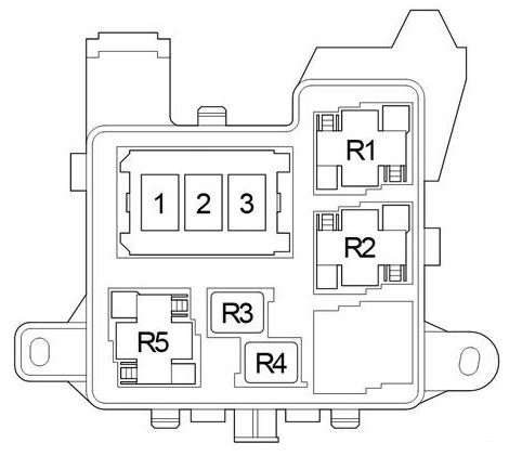
Marking
- 1 –
- 2 80A PTC2 – Heater
- 3 80A PTC1 – Heater
- R1 PTC heater relay (PTC1)
- R2 PTC heater relay (PTC2)
- R3 –
- R4 Until February 2012: Headlight (H-LP) / From February 2012: Daytime running lights (DRL).
- R5 Dimmer (DIM)