The first generation Citroen C4 was produced in 2004, 2005, 2006, 2007, 2008, 2009 and 2010 in various versions: hatchback, Picasso, etc. After the update, the 2nd generation was produced in 2011, 2012, 2013, 2014, 2015, 2016, 2017, 2018 and to the present. We will consider the fuses of the Citroen C4 with a detailed description of all the blocks and their location.

Depending on the configuration and year of manufacture, several options for block design and relay placement are possible.
Fuse blocks under the hood
Main unit with fuses
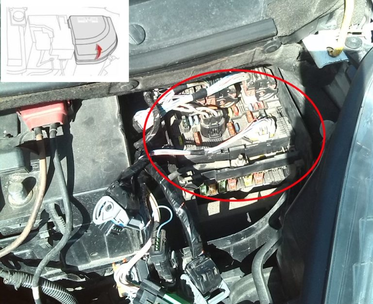
Located next to the battery. To access the fuse box in the engine compartment, detach and remove the protective cover.
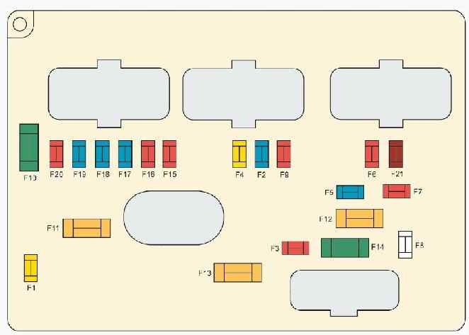
Option 1
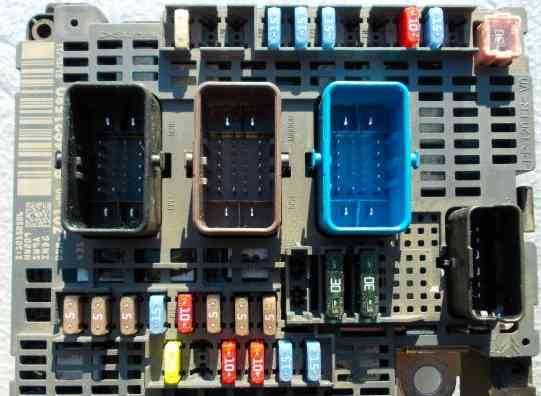
Description
- F1 15A Engine control computer – power supply protection and distribution unit
- F2 5A Electric fan group control unit
- F3 5A Engine control computer
- F5 15A Engine control computer
- F6 20A Engine control computer – fuel pump with fuel level sensor
- F7 10A Engine control computer
- F8 10A Engine control computer
- F10 5A Cruise control protection contactor – automatic transmission computer
- F11 15A Left headlight – right headlight – ionizer
- F14 25A Air conditioning compressor
- F15 5A Power steering pump mechanism
- F17 10A Electrochromic interior rearview mirror – driver’s door power window/exterior rearview mirror control board
- F19 30A Low/high speed windshield wiper
- F20 15A Windshield washer pump
- F21 20A Headlight washer pump
- F22 15A Audible signal
- F23 15A Right headlight
- F24 15A Left headlight
- F26 10A Air conditioning compressor
- F29 30A Starter
The following fuses are located separately (on the bottom side of the unit):
F10 5A Automatic transmission control group
F11 5A Shift-lock relay
F12 15A Automatic transmission computer
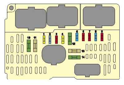
Option 2
Marking
- 20 A Engine control, engine cooling fan
- 15 A Audible signal
- 10 A Windshield and rear window washers
- 20 A Headlight Omivac
- 15 A Fuel pump
- 10 A automatic transmission, xenon lamps, controllable headlights, adsorber pumping solenoid valve
- 10 A ABS/ESP calculators, power steering
- 25 A Starter
- 10 A Auxiliary heating unit (diesel engine), coolant level sensor
- 30 A Engine solenoid valve, water in fuel sensor, engine calculator, injectors, ignition coil, lambda probe, adsorber purge solenoid valve (vehicles with 1.4i 16V and 1.6i 16V engines)
- 40 A Blower fan, air conditioning
- 30 A Front wiper
- 40 A BSI Block
- Not used
- 10 A Right high beam headlight
- 10 A Left high beam headlight
- 15 A Left dipped beam headlight
- 15 A Right dipped beam headlight
- 15 A Engine calculator (vehicles with 1.4i 16V and 1.6i 16V engines)
- 10 A Engine solenoid valves
- 5 A Engine cooling system electric fan relay, variable valve timing system
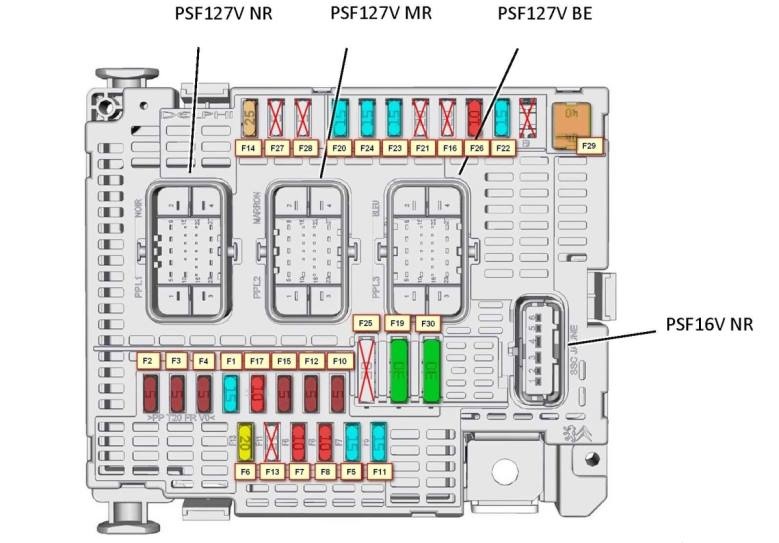
Option 3
Scheme
Transcript
- (20A) (Engine Control Unit – Engine Fan Group).
- (15A)(Beep).
- (10A)(Front and rear window washers).
- (20A(Headlight washer).
- (15A)(Fuel pump).
- (10A) (Automatic transmission – Xenon – Adjustable headlights – Absorber cleaning solenoid valve (2.0 engine).
- (10A) (ABS/ESP control units – Power steering).
- (20A)(Starter).
- (10A) (Additional heating control unit (diesel) – Coolant level contactor).
- (30A) (Engine solenoid valve – Water in diesel fuel sensor – Engine control unit – Injectors – Ignition coil – Oxygen sensor – Absorber purge solenoid valve (1.4 and 1.6 engines).
- (40A)(Air fan – Air conditioner).
- (30A)(front wiper).
- (40A) (Intelligent switching unit).
- (30A) (Air compressor (on 2.0 engine)).
Maxi fuses
These fuses are made in the form of fusible inserts and are located in the lower part of the block.
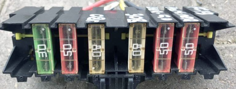
MF1 30 A / 50 A Engine cooling system electric fan
MF2 30 A ABS/ESP pump power supply
MF3 50 A ABS/ESP calculator
MF4 80 A BSI unit
MF5 80 A BSI unit
MF6 10 A Passenger compartment fuse box
MF7 20 A diesel fuel additive supply
MF8 Not used
Fuses on the battery
Photo – example of execution
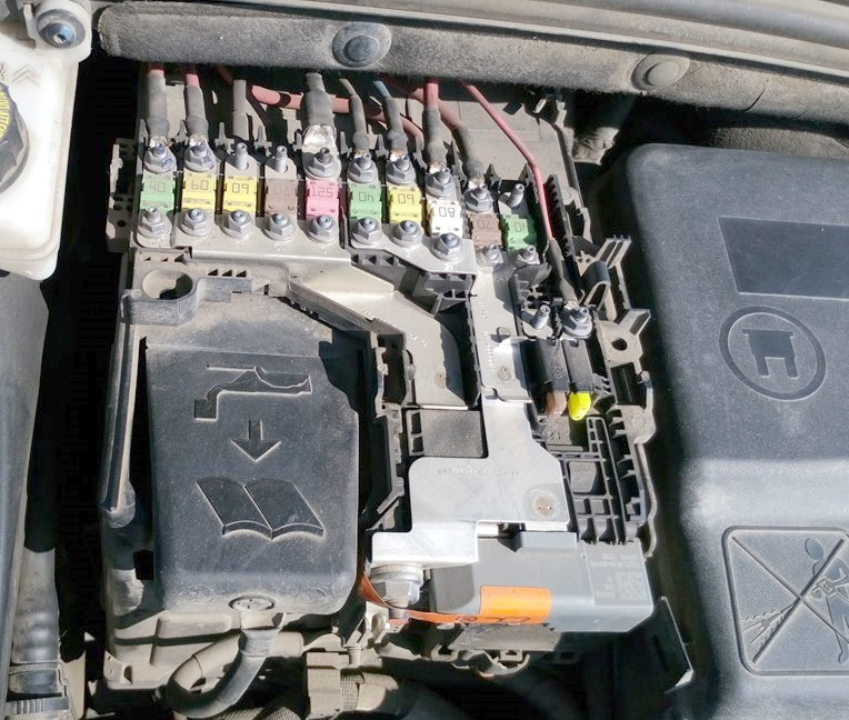
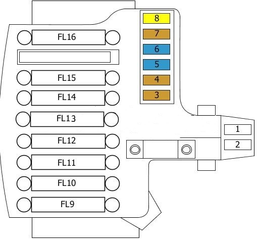
Description
| 1 | – |
| 2 | – |
| 3 | (5A) Battery status sensor |
| 4 | (5A) Electronic gearbox control unit |
| 5 | (5A/15A) Diagnostic Connector (DLC) |
| 6 | (15A) Electronic gearbox control unit |
| 7 | (5A) ABS ESP control unit |
| 8 | (20A) Rear 12V socket |
| FL9 | (60A) Fuses on BSI (Intelligent Power Distribution Module) |
| FL10 | (80A) Power steering |
| FL11 | (30A) Electronic gearbox control unit |
| FL12 | (60A) Cooling system fan motor |
| FL13 | (60A) Fuses on BSI (Intelligent Power Distribution Module) |
| FL14 | (70A) Glow plugs |
| FL15 | (100A) Relay Protection Unit 3 |
| FL16 | – |
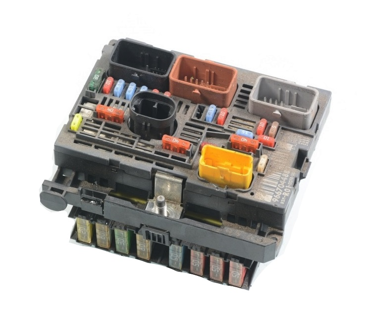
Option 2
Block diagram
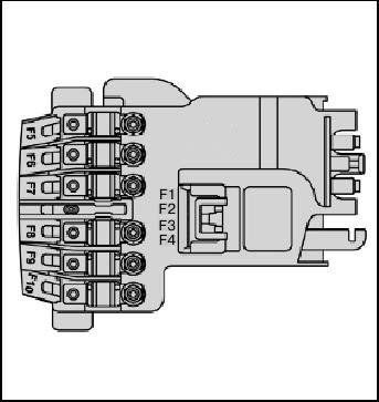
Appointment
- F1 Not used
- F2 30 A Transmission (electronically controlled manual or automatic)
- F3 Not used
- F4 Not used
- F5 80 A Power steering pump
- F6 70 A Heater unit (diesel engine)
- F7 100 A Protection and switching unit
- F8 Not used
- F9 30 A Electronically controlled manual transmission electric pump assembly
- F10 30 A Valvetronic system electric motor
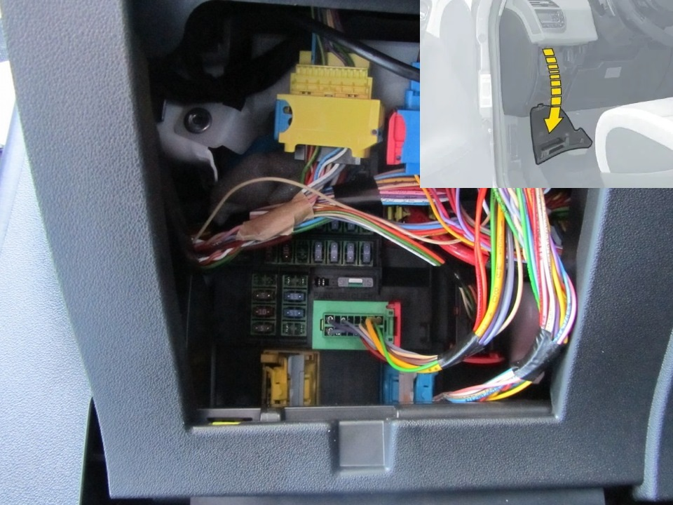
Fuses in the Citroen C4 cabin
They are located to the left of the driver under the dashboard. Access to them is closed by a decorative cover. In order to open this cover, you must: release the latches, for which pull it by the upper part, then remove the cover by turning 2 bolts by 1/4 turn, and fold the block. On the back of the frame there are special tweezers, with which you can easily dismantle any fuse.
Option 1
Block diagram
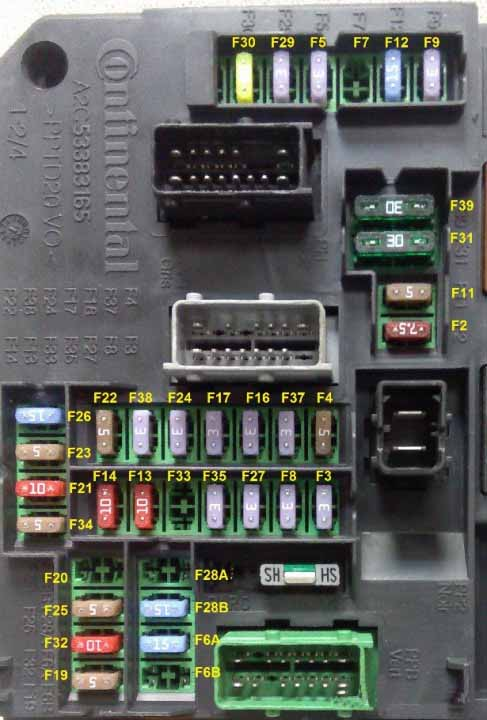
Fuse designations
F2 7.5A Diagnostic connector.
F3 3A Anti-theft device or START/STOP button.
F4 5A Remote key reader.
F5 3A Remote key.
F6A-F6B 15A Touch screen display, audio and navigation systems, CD player, USB and additional connectors.
F7 15A Hands-free starting aid electronic unit.
F8 3A Alarm siren, alarm processor.
F9 3A Steering wheel switch unit.
F11 5A Stability control calculator, alarm common switching unit, electronic key scanning device.
F12 15A Double brake pedal contactor.
F13 10A Front cigarette lighter.
F14 10A Rear cigarette lighter.
F16 3A Individual lamps, glove box lighting.
F17 3A Sun visor lighting, individual lights.
F19 5A Instrument panel.
F20 5A Electronically controlled manual transmission gear selector.
F21 10A Radio and air conditioning control.
F22 5A Displays, parking sensors.
F23 5A Engine compartment fuse module.
F24 3A Rain and light sensor.
F25 15A Airbag and pyrotechnic tensioner unit.
F26 15A
F27 3A Double brake pedal contactor.
F28A-F28B 15A Radio, car radio (optional).
F29 3A Steering column switch.
F30 20A Rear window wiper.
F31 30A Central locking, front and rear exterior and interior lock drive motors.
F32 10A Power supply for rear view camera in C4L China. (Output 16V NE 13pin), audio amplifier.
F33 3A Driver seat memory unit.
F34 5A Power steering relay.
F35 3A
F37 3A Driver door wiper/mirror control – electrochromic interior rear view mirror
F38 3A Headlight range adjuster switch – electrochromic rear view mirror.
F39 30A
Fuses 13 and 14 are responsible for the cigarette lighter.
Option 2
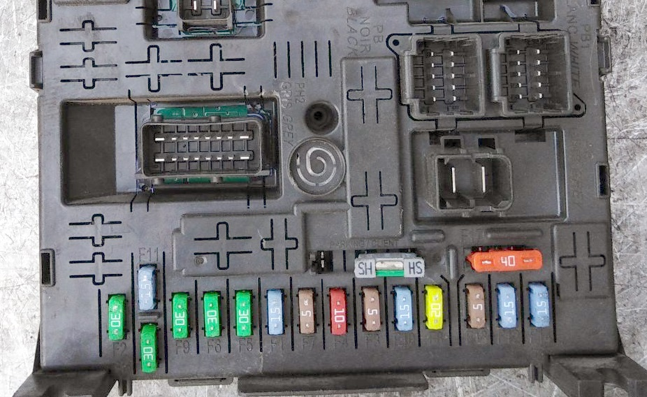
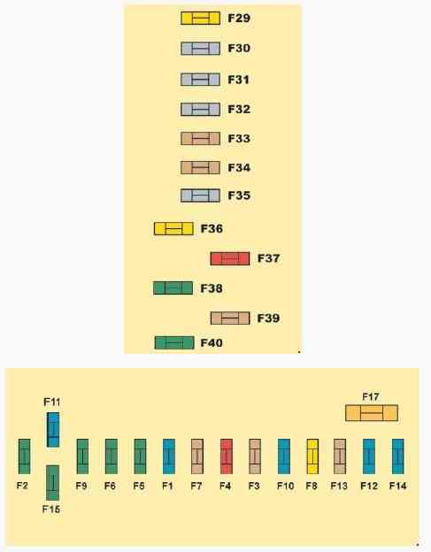
Transcript
- F1(15A) Rear wiper.
- F2(30A) Central locking – Deadlock.
- F3(5A) Airbags and pretensioners.
- F4(10A) Diagnostic circuit – Brake light switch – Electrochromic rearview mirror – Electronic Stability Program (ESP) – Water level sensor – Diesel fuel additives – Clutch pedal contactor (ESP, cruise control and speed limiter).
- F5(30A) Front windows – Heated and electrically operated rear-view mirrors.
- F6(30A) Rear windows.
- F7(5A) Interior lighting.
- F8(20A) Car radio – NaviDrive – Steering wheel controls – Display – Security alarm – Front 12V socket – Trailer connector – Driving school module.
- F9(30A) Cigarette lighter – Rear 12V socket.
- F10(15A) Tire pressure sensors – BVA – STOP contactor.
- F11(15A) Anti-theft steering lock – Diagnostic connector – Diesel particulate filter.
- F12(15A) Electric seat adjustment – Warning signal for unintentional crossing of the marking line – Parking sensors.
- F13(5A) Rain sensor – Light sensor – Electronically controlled manual transmission – Engine control unit.
- F14(15A) Air conditioning – Instrument panel – Tachometer – Airbags and pretensioners – Trailer connector – Bluetooth phone.
- F15(30A) Central locking – Deadlock.
- F16(SHUNT)( – ).
- F17(40A) Rear window heating.
- F29(20A) Seat heating.
- F33(4A) Parking assistance system, automatic activation of windscreen wipers and lighting.
- F36 (20A) Hi-fi amplifier.
- F37 (10A) Air conditioning.
- F38 (30A) Driver’s seat electric drive.
- F39 (5A) Filler flap.
- F40 (30A) Electric passenger seat, panoramic roof.
Fuses number 8 and 9 are responsible for the cigarette lighter.
Relay and fuse block – BFH3
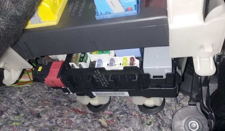
Located just below the main one.
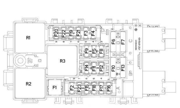
Block elements
| F3 | 15A fuse box in cabin 5 for taxi version |
| F4 | 15A 12V socket for multimedia equipment |
| F5 | 30A rear window lifter motors |
| F6 | 30A electric motors for front window lifts |
| F7 | 2A heated seats |
| F8 | 20A air conditioner fan |
| F9 | 30A electric trunk lid |
| F10 | 40A left seat belt coil |
| F11 | 5A trailer switch box |
| F12 | 30A driver’s seat power and massage device |
| F13 | 40A right seat belt coil |
| F14 | 30A handle replacement – passenger seat power – seat massage devices |
| F15 | 25A electric drive for the sunroof blind |
| F16 | 5A multiplex control board for the driver’s door power window/exterior rearview mirror |
| F17 | 10A lighting and memory unit for exterior rear-view mirrors |
| F18 | 25A audio amplifier |
| F19 | not used |
| F20 | 7.5A electric trunk lid |
| F21 | 3A “Hands-free” access and start unit |
| F2 | 7.5A electrically heated mirrors |
| F22 | 20A 230V socket |
| F23 | not used |
| R1 | 230 V socket |
| R2 | 12 V connector |
| R3 | not used |
| F1 | 40A rear window heater |
Individual relay and fuse elements can be installed outside these blocks and are located next to their protection device (for example, cooling fan relays, etc.).